 |
| The Breadboard Test Amp |
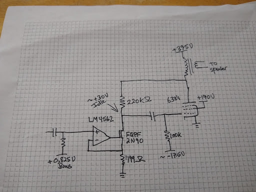
Below is the first circuit I tested. The idea here was to drive plate-to-grid output tube shunt feedback with an ideal transconductance amplifier (very high impedance output). Taken to its extreme, this approach can give up to 100% local feedback to the output stage. In this implementation, the output tube grid bias resistor spoils the feedback scheme, resulting in only ~30% output tube local feedback.
 |
| First Test Circuit |
Below is the resulting distortion spectrum at 1W into 8 Ohms.
 |
| 0.70% Distortion @ 1W |
Amplifier Zout was measured at 1.67 Ohms. This seems like a low-cost, simple SE amp with decent performance, but I wanted to see if I could fix the feedback current leak and get better results.
The next step was to add a mosfet grid driver for the output tube, since my eventual tube choice was going to need one to operate properly. This allowed me to use a much higher-valued bias resistor since mosfets have very-low gate leakage. The 100k resistance that was pulling current from the feedback is now a 3M resistance, which is more than an order of magnitude larger than the feedback resistor. This gives ~94% local feedback if my calculations are correct.
Below is the resulting distortion spectrum at 1W into 8 Ohms.
Amplifier Zout was measured at 1.1 Ohms. Things definitely got better.
 |
| Second Test Circuit |
Below is the resulting distortion spectrum at 1W into 8 Ohms.
 |
| 0.25% Distortion @ 1W |
Amplifier Zout was measured at 1.1 Ohms. Things definitely got better.
At this point, I had results that represented something close to the best one could get with a feedback loop that only involved the output stage. I wanted to do better. I wanted 0.1% distortion at 1W or better. I wanted less than 1 Ohm Zout. I knew that I'd have a harder time once I subbed the 826 since it has less transconductance than the 6384. I therefore abandoned the idea of output tube only feedback and decided to involve the driver stage as well in the feedback loop.
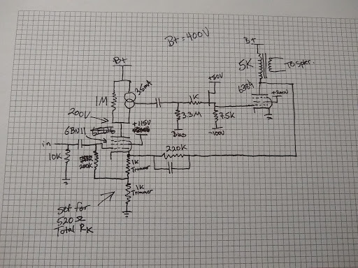
I decided to try feedback from the output tube plate to driver cathode. Below is the circuit:
 |
| Third and Fourth Test Circuits |
I used 6EW6 and 6BN11 (they are equivalent but I switched over to the 6BN11 because that's what I eventually plan to use) as driver tubes. I loaded it with a CCS in parallel with a resistor. The resistor reduces gain a bit with the goal of reducing plate voltage drift.
In my third test, I used a 440k resistor in parallel with the CCS. The schematic shows 1M there, because that ended up working better but just imagine a 440k there for now. This gave the driver a gain of ~360 (measured with output tube removed). 1W distortion result below:
 |
| 0.27% Distortion @ 1W |
This ended up being very close to the same result I got with the second test circuit above. In fact, I though I had some measurement setup issue since results at every power level were very similar. Then I though about it more. The gain of the driver was equal to the overall gain I was trying to set with my feedback divider. This means that the excess gain (applied as feedback) was equal to the gain of the output stage. All of the output stage gain was going to feedback, which is very similar to the configuration in the second test setup. Ok, so that kind of makes sense.
I decided to see what I could do to increase gain a bit further and I ended up replacing the 440k resistor with a 1M. This increased driver gain to ~560. 1W distortion below:
On this one I stopped to measure Zout which came out to 0.8 Ohms. This is really starting to get into the ballpark of the performance I was looking for. Part of me worried that the 826 would distort more and so I wanted some more margin if I could get it and I had one more idea to try.
 |
| 0.14% Distortion @ 1W |
On this one I stopped to measure Zout which came out to 0.8 Ohms. This is really starting to get into the ballpark of the performance I was looking for. Part of me worried that the 826 would distort more and so I wanted some more margin if I could get it and I had one more idea to try.
 |
| Fifth Test Circuit |
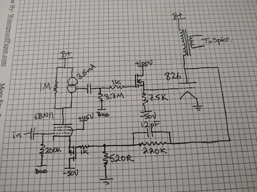
This circuit was very similar except it has a p-channel FET that buffers the feedback network from the cathode of the 6BN11. AC cathode current variations in the 6BN11 (which include plate and screen current variations) end up making their way into the feedback network in the third/fourth test circuit. This was my attempt to separate them and provide a low impedance point for the 6BN11 cathode to avoid cathode degeneration in that stage, which reduces gain.
This change resulted in a gain of ~2600 in the input stage (quite an increase!). One thing to note here is that plate voltage drifts with time in this configuration due to the high gain. A bias servo circuit will probably be necessary to build this into a working amplifier. 1W distortion below:
Zout was measured at 0.6 Ohms. This is very low, considering copper losses account for ~0.55 Ohms and cannot be corrected for by the feedback, since the output transformer is outside the loop. At this point, I considered the circuit plenty good enough.
 |
| 0.046% Distortion @ 1W |
Zout was measured at 0.6 Ohms. This is very low, considering copper losses account for ~0.55 Ohms and cannot be corrected for by the feedback, since the output transformer is outside the loop. At this point, I considered the circuit plenty good enough.
I then substituted the 826 output tube and results can be seen here. Distortion went down even further (to 0.027%), presumably due to the great linearity of the 826 (thank goodness). The 826 only has 2/3 the transconductance of the 6384 and 1/3 the gain in-circuit so I was worried it might go up. The Zout with the 826 was ~0.7 Ohms, which makes sense with the lower transconductance.
Anyway, I hope that explains the progression I went through to arrive at this approach.


