And when I claim ultra-low distortion, I'm getting 0.027% THD at 1W. As of the time of writing this, I'm unaware of any other series-feed SE tube amp that does better.
It's currently a breadboard amp with a very sophisticated forced air cooling system. ;)
 |
| The Amp |
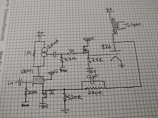
Here's a simplified schematic:
 |
| Simplified Schematic |
I'm currently running B+ at 520V. Output transformer is an Edcor 5k:8. Nothing exotic.
I'll walk through the theory of operation. I chose a 60W high-impedance directly-heated transmitting triode. It needs a positive grid bias and a low-impedance grid drive. This is provided by the N-channel mosfet. I'm running the 826 at 100mA (52W dissipation). When I get a new power transformer, I will try a bias point with a little more current and voltage, closer to the 60W limit. As it stands now, the 520V, 100mA operating point clips very symmetrically.
The input stage is designed to provide maximum gain and take feedback from the plate of the ouput tube. This allows us to reduce distortion a lot, but since the output transformer is outside the feedback loop, an expensive, exotic, high bandwidth output transformer is not needed for us to apply a robust feedback factor.
The 6BN11 (dual version of the 6EW6) has decent transconductance and develops a gain of ~2600 in this circuit. I'm sure there are many other small pentodes that would do just as well in this position. The p-channel FET source follower drives the cathode of the 6BN11. This isolates the feedback divider from the AC cathode currents of the input stage. The resulting low impedance drive of the feedback to the 6BN11 cathode results in over a 3X distortion reduction over tying the 6BN11 directly to the 520R feedback resistor. The traditional approach of connecting the cathode to the feedback network allows AC plate and screen currents in the input stage to corrupt the effectiveness of the feedback. A drawback to the high gain of the input stage is that bias stability isn't very good. The final version of this amplifier will probably require a bias servo on that stage. I have observed 100V drift in plate voltage in a listening session.
Sensitivity of the overall amplifier is set to ~0.7V. This can be easily changed by altering the 520R/220k resistor ratio.
I calculated ~23W output with a lossless transformer. In actual testing I got 19W when it started to clip. Seems about right for real-world loss. I mean, I really wish I had gotten to 20W, because that sounds a lot bigger than 19W, but I'll have to live with that disappointment, I guess.
See below for distortion measurements at different power levels:
 |
| 0.014% @ 100mW |
 |
| 0.017% @ 500mW |
 |
| 0.027% @ 1W |
 |
| 0.040% @ 2W |
 |
| 0.063% @ 5W |
 |
| 0.063% @ 10W |
 |
| 0.30% @ 19W |
I measured Zout at 0.7 Ohms, so damping factor is over 10, which is probably pretty unusual for a SET amp.
Here's a 10 kHz square wave:
Blue trace is the output transformer primary, yellow is the secondary. Both have a nice shape, but you can see how the output transformer affects the signal.
Here's a screenshot I took of the input tube plate waveform at 19W output:
You can see the hump forming on the positive-going side where we are starting to hit saturation in the output tube. The negative side is also forming a "point." I didn't capture an image, but further increases in level cause sharp spikes to form on the positive and negative sides, indicating symmetrical clipping. It's a good operating point for this supply voltage. I didn't dwell too long in that state for fear of over-stressing the output tube grid.
I think I covered everything. To close things out, I'll attach some pictures of the 826 and the 6BN11 operating in the dark. One of the requirements for this amp was to have tubes that look good. I think I succeeded on that.


Positive Grid Bias
ReplyDeleteI am very impressed with your post because this post is very beneficial for me