Thursday, July 30, 2020

If UNSET and the RCA50W Had a Baby

What's UNSET? See here. It's a clever way of wrapping series-applied voltage feedback around an output stage and sharing some of the idle dissipation in the output stage between a mosfet follower and the output tube (which can get you more power if you increase B+ accordingly), apparently recently discovered by Mr. Tubelab and Mr. Smoking-Amp nearly simultaneously. 

What's the RCA 50W amp?  See below:


It's a 50W push-pull amp with three nested feedback loops that apparently can do 50W@0.1% THD, which ain't too shabby. The innermost loop is parallel-applied voltage feedback from plate to grid of the output tube. Surrounding that is series-applied voltage feedback from plate of output tube to driver cathode. And then there is the global loop that goes from amplifier output to input tube.

I've always had mixed feelings about this amp. It has a lot done right, but my back-of-the-envelope calculations show that the ouput tube plate to driver cathode feedback can't be very effective due to the fact that the low impedance load at the plate of the driver spoils a lot of the potential driver gain. Driver cathode degeneration lowers gain further. I'm not even totally sure that it has more gain than the gain that is trying to be set with the resistor ratio that is there.

Anyway, I've been playing with output tube plate to driver cathode feedback and have been having exceptional results with high gain drivers. It makes me wonder what would happen if we fixed the RCA amp a bit and used series-applied voltage feedback around the output tube instead of parallel-applied feedback, so I decided to run with that idea and here is a simplified conceptual schematic:

I made the output tubes two KT88 UNSETs (UNPPTs?), which frees up the driver to use a very high impedance load and develop some serious gain. Oh yeah. 

This is pretty similar to my driver for my recent 826 SE amp experiments, only I reversed the input and feedback connections to make the phasing correct for negative feedback. Bias on the 6BN11 stage is not very stable over time due to absurdly-high gain, so a bias servo is probably mandatory on that stage. Open-loop gain of that stage is ~2600. This provides a lot of feedback and I expect resulting driving impedance on the primary of the transformer will be somewhere between 10 and 20 Ohms. Using a Hammond 1650R (or something with similar low copper losses) will result in a Zout of ~0.5 Ohms or so. Distortion will be extremely low. 

In my mind, at that point, global feedback is optional, so I have omitted it. It could be added back in with another gain stage. I also like input transformers for the immunity to ground loops that they offer so I included one. Obviously, I have omitted some necessary components such as stoppers, protection diodes, and something to tie input transformer secondary to some level other than what the leakage currents pull it to.

The UNSET output configuration offers the opportunity to share some of the idle dissipation between the mosfet and the power tube, so I have increased B+ to 530V. This still puts 450V across the output tubes like in the RCA amp, but now we can hit over 75W with the same class of output tube, and have plenty of idle current to keep idle output tube transconductance high.

I decided to pull the output tube plate to driver grid feedback network down near GND with a CCS. My intuition tells me that having a high AC impedance at this node would have a balancing effect on the amplifier. I'm not sure how well this would work (haven't simmed it or anything). The other option would be to ground the center point (maybe with a trim pot in the center to adjust out AC imbalances in the two halves).

Anyway, I think it would make a good amp that could make your ears bleed with low distortion.

Wednesday, July 29, 2020

Unity-Coupled Plitron Amp Revisited

I decided to re-work my Unity-Coupled amplifier that I wrote up here


One thing that always bothered me was that I used a split-rail supply (-300V/+500V) to get 800V total supply voltage for the 841 tubes, which left the grid circuit of the 841 referenced to a negative supply and coupling any power supply noise directly into the 841 grid circuit. The supplies were Maida-style regulators so are pretty good but are not perfect. 

Another thing that bothered me was ground loops. I find background hum/buzz to be more objectionable than distortion, quite honestly, and I was having difficulty getting rid of it all. 

I also had some random rustling sounds in the amp, which seem to be most commonly a symptom of a bad solder joint. Unfortunately, this was a very complex amp so finding a bad solder joint is not easy, but it did make me want to get in there and change things with the hope of finding and fixing that issue.

I settled on a few things to change:

1. Reference 841 stage to GND.
2. Re-do grounding. This amp has seen too many changes and grounding scheme has suffered.
3. Input transformers to totally prevent ground loops from ever happening in equipment interconnects.
4. New input board due to space constraints and the fact that I want to put some things I'd learned using op-amps into practice. 

Below is the new configuration for the tube section:


The 841 stage cathode is now tied to GND, rather than a negative supply. The CCS plate load is supplied from the opposite side output tube plate. In McIntosh amps, this resulted in a little bit of positive feedback to the driver. It increased gain by giving the plate load a higher dynamic impedance. In this circuit, the driver gain is unchanged because the driver already had a CCS plate load. The CCS impedance probably goes up some, but I don't expect that it makes any difference in the gain of the driver. In this amplifier, it's just a free HV supply that always stays 60V above the driver plate voltage.

The 841 is now driven by a solid-state op-amp circuit detailed below. The 841 requires the grid to be driven positive with low distortion (Class A2 operation) and I wanted to try a new approach and see if I could reduce distortion.

The rest of it is a pretty straightforward implementation of a Unity-Coupled output stage with a source follower driver and a mosfet that drops the screen voltage. 460V is a higher screen voltage than necessary for the load that the PAT-1070-UC presents, so it is beneficial to lower it.

Below is the solid-state op amp input section of the amplifier: 


All op-amps used were LME49860s powered by +-18V. The LME49860 is very similar to the LM4562 but is a little more expensive and can handle a little higher supply voltage, which I thought would be beneficial.

A Jensen JT-11P-1 input transformer with recommended snubber network feed opposite phase non-inverting amps. This feeds a follower that drives the grid of the 841. Bias is presented to the non-inverting input and the feedback scheme around the follower is designed to help the op-amp deal gracefully with the ~300pF load the 841 grid presents. 

I added an AC balance adjustment (the 10R pot) to allow adjustment for gain mismatches in the two phases of the amplifier. I didn't expect perfect matching of the 841s and made an adjustment to compensate. 

Here are pictures of the op-amp boards:


The first stage is on the manufactured board. The second stage is on the prototype board. I wasn't likely to ever need something exactly like this again so I just hand wired it. Each 841 has its own bias adjustment. 

I used cheap AC-DC 18V isolated output switching supplies to generate the +-18V. I constructed a CLC filter to clean up the ripple on the output and got great results. Below is a screen shot of filter input and filter output:


After implementing the new input stage and the changes to the tube section, all of the background buzz was gone from one channel. That both excited me and disappointed me. I was hoping it would be gone from both. 

So next I set out to redo the grounding. I re-did everything with a nice bus bar, but still there was buzz in one channel with a 120Hz ripple waveform visible on the output of that channel. I couldn't tell where exactly it was originating from but I isolated it to the output stage and just decided to build two new output tube boards. I replaced them both and the buzz went away. Not sure what was bad, but problem is now gone and no more random rustling sounds, either. 

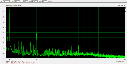
Below are distortion results:

100mW

500mW

1W

2W

5W

10W

Distortion is pretty good for an open-loop amp, but I've got plans to make it much better when my 841s wear out some day. For now, I just like the way they look too much to get rid of them.

I didn't measure Zout this time, but I didn't change anything that should affect that, so it should still be ~1.1 Ohm.

The amp clips at about 40W. I was using the balanced output from my USB soundcard to drive the amp for the distortion test and I didn't realize that it only puts out .7Vrms max, so it didn't have enough output to drive the amp all the way to clipping. I designed to a 2Vrms sensitivity since the source that I use with this amp puts that out with no trouble. I'll have to wire this up so that my Pete Millett soundcard interface can drive it to clipping when I get some more time and update this post with more measurements.

The amp is so much more satisfying to listen to now. I mean, I can't say that I notice a difference in distortion but having the background be totally silent is such an improvement.