Wednesday, August 5, 2020

My 6384 SE Experiments

In this post I'd like to detail a series of experiments that led to the design of the 826 amp that I wrote about in my last post. I investigated several circuits using a 6384 output tube, with the intention of eventually subbing in the 826 after I figured out what worked the best. The 6384 is basically like a 6L6GC, but built to survive the apocalypse and with a different pin out and a little more sensitive screen grid. For all of these experiments, I ran the 6384 at ~70mA into a 5K output transformer at 395V. Clipping occurred at a little over 10W.

The Breadboard Test Amp

Below is the first circuit I tested. The idea here was to drive plate-to-grid output tube shunt feedback with an ideal transconductance amplifier (very high impedance output). Taken to its extreme, this approach can give up to 100% local feedback to the output stage. In this implementation, the output tube grid bias resistor spoils the feedback scheme, resulting in only ~30% output tube local feedback. 
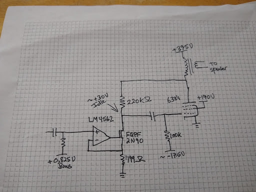
First Test Circuit

Below is the resulting distortion spectrum at 1W into 8 Ohms. 

0.70% Distortion @ 1W

Amplifier Zout was measured at 1.67 Ohms. This seems like a  low-cost, simple SE amp with decent performance, but I wanted to see if I could fix the feedback current leak and get better results.

The next step was to add a mosfet grid driver for the output tube, since my eventual tube choice was going to need one to operate properly. This allowed me to use a much higher-valued bias resistor since mosfets have very-low gate leakage. The 100k resistance that was pulling current from the feedback is now a 3M resistance, which is more than an order of magnitude larger than the feedback resistor. This gives ~94% local feedback if my calculations are correct.

Second Test Circuit

Below is the resulting distortion spectrum at 1W into 8 Ohms. 

0.25% Distortion @ 1W

Amplifier Zout was measured at 1.1 Ohms. Things definitely got better.

At this point, I had results that represented something close to the best one could get with a feedback loop that only involved the output stage. I wanted to do better. I wanted 0.1% distortion at 1W or better. I wanted less than 1 Ohm Zout. I knew that I'd have a harder time once I subbed the 826 since it has less transconductance than the 6384. I therefore abandoned the idea of output tube only feedback and decided to involve the driver stage as well in the feedback loop. 

I decided to try feedback from the output tube plate to driver cathode. Below is the circuit:
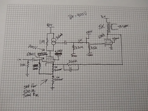
Third and Fourth Test Circuits

I used 6EW6 and 6BN11 (they are equivalent but I switched over to the 6BN11 because that's what I eventually plan to use) as driver tubes. I loaded it with a CCS in parallel with a resistor. The resistor reduces gain a bit with the goal of reducing plate voltage drift. 

In my third test, I used a 440k resistor in parallel with the CCS. The schematic shows 1M there, because that ended up working better but just imagine a 440k there for now. This gave the driver a gain of ~360 (measured with output tube removed). 1W distortion result below:

0.27% Distortion @ 1W

This ended up being very close to the same result I got with the second test circuit above. In fact, I though I had some measurement setup issue since results at every power level were very similar. Then I though about it more. The gain of the driver was equal to the overall gain I was trying to set with my feedback divider. This means that the excess gain (applied as feedback) was equal to the gain of the output stage. All of the output stage gain was going to feedback, which is very similar to the configuration in the second test setup. Ok, so that kind of makes sense.

I decided to see what I could do to increase gain a bit further and I ended up replacing the 440k resistor with a 1M. This increased driver gain to ~560. 1W distortion below:


0.14% Distortion @ 1W

On this one I stopped to measure Zout which came out to 0.8 Ohms. This is really starting to get into the ballpark of the performance I was looking for. Part of me worried that the 826 would distort more and so I wanted some more margin if I could get it and I had one more idea to try.

Fifth Test Circuit

This circuit was very similar except it has a p-channel FET that buffers the feedback network from the cathode of the 6BN11. AC cathode current variations in the 6BN11 (which include plate and screen current variations) end up making their way into the feedback network in the third/fourth test circuit. This was my attempt to separate them and provide a low impedance point for the 6BN11 cathode to avoid cathode degeneration in that stage, which reduces gain.

This change resulted in a gain of ~2600 in the input stage (quite an increase!). One thing to note here is that plate voltage drifts with time in this configuration due to the high gain. A bias servo circuit will probably be necessary to build this into a working amplifier. 1W distortion below:

0.046% Distortion @ 1W

Zout was measured at 0.6 Ohms. This is very low, considering copper losses account for ~0.55 Ohms and cannot be corrected for by the feedback, since the output transformer is outside the loop. At this point, I considered the circuit plenty good enough. 

I then substituted the 826 output tube and results can be seen here. Distortion went down even further (to 0.027%), presumably due to the great linearity of the 826 (thank goodness). The 826 only has 2/3 the transconductance of the 6384 and 1/3 the gain in-circuit so I was worried it might go up. The Zout with the 826 was ~0.7 Ohms, which makes sense with the lower transconductance. 

Anyway, I hope that explains the progression I went through to arrive at this approach.

Tuesday, August 4, 2020

An Ultra-Low Distortion 826 SE Amp

And when I claim ultra-low distortion, I'm getting 0.027% THD at 1W. As of the time of writing this, I'm unaware of any other series-feed SE tube amp that does better.

It's currently a breadboard amp with a very sophisticated forced air cooling system. ;)

The Amp

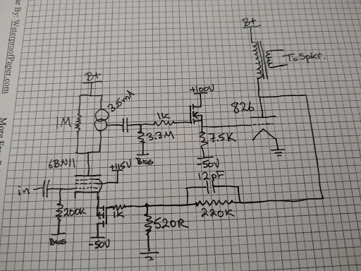
Here's a simplified schematic:

Simplified Schematic

I'm currently running B+ at 520V. Output transformer is an Edcor 5k:8. Nothing exotic. 

I'll walk through the theory of operation. I chose a 60W high-impedance directly-heated transmitting triode. It needs a positive grid bias and a low-impedance grid drive. This is provided by the N-channel mosfet. I'm running the 826 at 100mA (52W dissipation). When I get a new power transformer, I will try a bias point with a little more current and voltage, closer to the 60W limit. As it stands now, the 520V, 100mA operating point clips very symmetrically. 

The input stage is designed to provide maximum gain and take feedback from the plate of the ouput tube. This allows us to reduce distortion a lot, but since the output transformer is outside the feedback loop, an expensive, exotic, high bandwidth output transformer is not needed for us to apply a robust feedback factor. 

The 6BN11 (dual version of the 6EW6) has decent transconductance and develops a gain of ~2600 in this circuit. I'm sure there are many other small pentodes that would do just as well in this position. The p-channel FET source follower drives the cathode of the 6BN11. This isolates the feedback divider from the AC cathode currents of the input stage. The resulting low impedance drive of the feedback to the 6BN11 cathode results in over a 3X distortion reduction over tying the 6BN11 directly to the 520R feedback resistor. The traditional approach of connecting the cathode to the feedback network allows AC plate and screen currents in the input stage to corrupt the effectiveness of the feedback. A drawback to the high gain of the input stage is that bias stability isn't very good. The final version of this amplifier will probably require a bias servo on that stage. I have observed 100V drift in plate voltage in a listening session. 

Sensitivity of the overall amplifier is set to ~0.7V. This can be easily changed by altering the 520R/220k resistor ratio. 

I calculated ~23W output with a lossless transformer. In actual testing I got 19W when it started to clip. Seems about right for real-world loss. I mean, I really wish I had gotten to 20W, because that sounds a lot bigger than 19W, but I'll have to live with that disappointment, I guess.

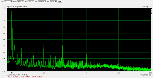
See below for distortion measurements at different power levels:

0.014% @ 100mW

0.017% @ 500mW

0.027% @ 1W

0.040% @ 2W

0.063% @ 5W

0.063% @ 10W

0.30% @ 19W

I measured Zout at 0.7 Ohms, so damping factor is over 10, which is probably pretty unusual for a SET amp. 

Here's a 10 kHz square wave:


Blue trace is the output transformer primary, yellow is the secondary. Both have a nice shape, but you can see how the output transformer affects the signal.

Here's a screenshot I took of the input tube plate waveform at 19W output:


You can see the hump forming on the positive-going side where we are starting to hit saturation in the output tube. The negative side is also forming a "point." I didn't capture an image, but further increases in level cause sharp spikes to form on the positive and negative sides, indicating symmetrical clipping. It's a good operating point for this supply voltage. I didn't dwell too long in that state for fear of over-stressing the output tube grid.

I think I covered everything. To close things out, I'll attach some pictures of the 826 and the 6BN11 operating in the dark. One of the requirements for this amp was to have tubes that look good. I think I succeeded on that.


Monday, August 3, 2020

Idea for Ultra-Low Distortion Unity-Coupled Amp


I had some great results in experiments with an SE amp design. In that amp, I took feedback from the output tube plate and applied it to a high-gain pentode/p-channel FET input stage. This gave fantastic results. The amp had very low distortion and Zout. (0.027% THD @ 1W and 0.7 Ohms)

This got me thinking about applying this approach to push-pull amps and here is what I came up with for a Unity-Coupled amp. A couple of things stand out:
  1. Feedback from the output stage plate can be taken from the output tube cathode, since cathode and anode swings are equal in magnitude. The great thing about this is that the cathode sits near GND potential at idle so you don't have a bunch of power dissipated in the feedback resistor at idle. 
  2. Creating a feedback network that works to restore balance in the amp is easy since the feedback network idles at a low voltage. The feedback network can be direct-coupled without needing to be pulled down to something near the input stage grid or cathode potential. It's already there. This makes the input stage work similar to the input stage of an instrumentation amp.
I drive the cathode of the input tube with a p-channel FET here and use the grid as the feedback node, and I configure the feedback network like the input stage of an instrumentation amplifier to correct imbalance in the amplifier.

The source follower drivers for the output tubes aren't really necessary. They simply reflect the way the output stage in my Unity-Coupled amplifier is currently configured. I like the immunity to blocking distortion that they offer so I will keep them there. 

The Plitron transformers have pretty low DCRs in the windings so I expect that this amplifier would deliver very low distortion and a Zout of less than 0.4 Ohms, even without feedback around the output transformer.

Some day I'll work something like this into my Unity-Coupled amplifier.

Thursday, July 30, 2020

If UNSET and the RCA50W Had a Baby

What's UNSET? See here. It's a clever way of wrapping series-applied voltage feedback around an output stage and sharing some of the idle dissipation in the output stage between a mosfet follower and the output tube (which can get you more power if you increase B+ accordingly), apparently recently discovered by Mr. Tubelab and Mr. Smoking-Amp nearly simultaneously. 

What's the RCA 50W amp?  See below:


It's a 50W push-pull amp with three nested feedback loops that apparently can do 50W@0.1% THD, which ain't too shabby. The innermost loop is parallel-applied voltage feedback from plate to grid of the output tube. Surrounding that is series-applied voltage feedback from plate of output tube to driver cathode. And then there is the global loop that goes from amplifier output to input tube.

I've always had mixed feelings about this amp. It has a lot done right, but my back-of-the-envelope calculations show that the ouput tube plate to driver cathode feedback can't be very effective due to the fact that the low impedance load at the plate of the driver spoils a lot of the potential driver gain. Driver cathode degeneration lowers gain further. I'm not even totally sure that it has more gain than the gain that is trying to be set with the resistor ratio that is there.

Anyway, I've been playing with output tube plate to driver cathode feedback and have been having exceptional results with high gain drivers. It makes me wonder what would happen if we fixed the RCA amp a bit and used series-applied voltage feedback around the output tube instead of parallel-applied feedback, so I decided to run with that idea and here is a simplified conceptual schematic:

I made the output tubes two KT88 UNSETs (UNPPTs?), which frees up the driver to use a very high impedance load and develop some serious gain. Oh yeah. 

This is pretty similar to my driver for my recent 826 SE amp experiments, only I reversed the input and feedback connections to make the phasing correct for negative feedback. Bias on the 6BN11 stage is not very stable over time due to absurdly-high gain, so a bias servo is probably mandatory on that stage. Open-loop gain of that stage is ~2600. This provides a lot of feedback and I expect resulting driving impedance on the primary of the transformer will be somewhere between 10 and 20 Ohms. Using a Hammond 1650R (or something with similar low copper losses) will result in a Zout of ~0.5 Ohms or so. Distortion will be extremely low. 

In my mind, at that point, global feedback is optional, so I have omitted it. It could be added back in with another gain stage. I also like input transformers for the immunity to ground loops that they offer so I included one. Obviously, I have omitted some necessary components such as stoppers, protection diodes, and something to tie input transformer secondary to some level other than what the leakage currents pull it to.

The UNSET output configuration offers the opportunity to share some of the idle dissipation between the mosfet and the power tube, so I have increased B+ to 530V. This still puts 450V across the output tubes like in the RCA amp, but now we can hit over 75W with the same class of output tube, and have plenty of idle current to keep idle output tube transconductance high.

I decided to pull the output tube plate to driver grid feedback network down near GND with a CCS. My intuition tells me that having a high AC impedance at this node would have a balancing effect on the amplifier. I'm not sure how well this would work (haven't simmed it or anything). The other option would be to ground the center point (maybe with a trim pot in the center to adjust out AC imbalances in the two halves).

Anyway, I think it would make a good amp that could make your ears bleed with low distortion.

Wednesday, July 29, 2020

Unity-Coupled Plitron Amp Revisited

I decided to re-work my Unity-Coupled amplifier that I wrote up here


One thing that always bothered me was that I used a split-rail supply (-300V/+500V) to get 800V total supply voltage for the 841 tubes, which left the grid circuit of the 841 referenced to a negative supply and coupling any power supply noise directly into the 841 grid circuit. The supplies were Maida-style regulators so are pretty good but are not perfect. 

Another thing that bothered me was ground loops. I find background hum/buzz to be more objectionable than distortion, quite honestly, and I was having difficulty getting rid of it all. 

I also had some random rustling sounds in the amp, which seem to be most commonly a symptom of a bad solder joint. Unfortunately, this was a very complex amp so finding a bad solder joint is not easy, but it did make me want to get in there and change things with the hope of finding and fixing that issue.

I settled on a few things to change:

1. Reference 841 stage to GND.
2. Re-do grounding. This amp has seen too many changes and grounding scheme has suffered.
3. Input transformers to totally prevent ground loops from ever happening in equipment interconnects.
4. New input board due to space constraints and the fact that I want to put some things I'd learned using op-amps into practice. 

Below is the new configuration for the tube section:


The 841 stage cathode is now tied to GND, rather than a negative supply. The CCS plate load is supplied from the opposite side output tube plate. In McIntosh amps, this resulted in a little bit of positive feedback to the driver. It increased gain by giving the plate load a higher dynamic impedance. In this circuit, the driver gain is unchanged because the driver already had a CCS plate load. The CCS impedance probably goes up some, but I don't expect that it makes any difference in the gain of the driver. In this amplifier, it's just a free HV supply that always stays 60V above the driver plate voltage.

The 841 is now driven by a solid-state op-amp circuit detailed below. The 841 requires the grid to be driven positive with low distortion (Class A2 operation) and I wanted to try a new approach and see if I could reduce distortion.

The rest of it is a pretty straightforward implementation of a Unity-Coupled output stage with a source follower driver and a mosfet that drops the screen voltage. 460V is a higher screen voltage than necessary for the load that the PAT-1070-UC presents, so it is beneficial to lower it.

Below is the solid-state op amp input section of the amplifier: 


All op-amps used were LME49860s powered by +-18V. The LME49860 is very similar to the LM4562 but is a little more expensive and can handle a little higher supply voltage, which I thought would be beneficial.

A Jensen JT-11P-1 input transformer with recommended snubber network feed opposite phase non-inverting amps. This feeds a follower that drives the grid of the 841. Bias is presented to the non-inverting input and the feedback scheme around the follower is designed to help the op-amp deal gracefully with the ~300pF load the 841 grid presents. 

I added an AC balance adjustment (the 10R pot) to allow adjustment for gain mismatches in the two phases of the amplifier. I didn't expect perfect matching of the 841s and made an adjustment to compensate. 

Here are pictures of the op-amp boards:


The first stage is on the manufactured board. The second stage is on the prototype board. I wasn't likely to ever need something exactly like this again so I just hand wired it. Each 841 has its own bias adjustment. 

I used cheap AC-DC 18V isolated output switching supplies to generate the +-18V. I constructed a CLC filter to clean up the ripple on the output and got great results. Below is a screen shot of filter input and filter output:


After implementing the new input stage and the changes to the tube section, all of the background buzz was gone from one channel. That both excited me and disappointed me. I was hoping it would be gone from both. 

So next I set out to redo the grounding. I re-did everything with a nice bus bar, but still there was buzz in one channel with a 120Hz ripple waveform visible on the output of that channel. I couldn't tell where exactly it was originating from but I isolated it to the output stage and just decided to build two new output tube boards. I replaced them both and the buzz went away. Not sure what was bad, but problem is now gone and no more random rustling sounds, either. 

Below are distortion results:

100mW

500mW

1W

2W

5W

10W

Distortion is pretty good for an open-loop amp, but I've got plans to make it much better when my 841s wear out some day. For now, I just like the way they look too much to get rid of them.

I didn't measure Zout this time, but I didn't change anything that should affect that, so it should still be ~1.1 Ohm.

The amp clips at about 40W. I was using the balanced output from my USB soundcard to drive the amp for the distortion test and I didn't realize that it only puts out .7Vrms max, so it didn't have enough output to drive the amp all the way to clipping. I designed to a 2Vrms sensitivity since the source that I use with this amp puts that out with no trouble. I'll have to wire this up so that my Pete Millett soundcard interface can drive it to clipping when I get some more time and update this post with more measurements.

The amp is so much more satisfying to listen to now. I mean, I can't say that I notice a difference in distortion but having the background be totally silent is such an improvement.

Monday, April 24, 2017

How to Make a Pentode Voltage Amplifier That is More Linear Than Any Triode

It is generally accepted that pentodes are on average a good bit less linear as voltage amplifiers than triodes. Today I'm going to show how to take a pentode and make it more linear than any triode, or at least any triode that I have any experience with (if there is one that beats this performance, I wouldn't mind knowing about it).

I've previously written on this blog about highly-linear power stages using KT88s. The approach here will be similar, using voltage feedback that is parallel applied and driven with a p-channel FET, so the overall input impedance of the circuit will be very high and easy to drive. The p-channel FET makes things work out with a minimum of components. There are other variations of this circuit that would be possible with n-channel devices or tube followers/active loads should one desire to keep it all tubes.

Conceptually, this is kind of what I'm attempting to do as far as feedback scheme goes:


And here is a more fleshed-out conceptual drawing of the actual circuit:


What I've done is make a very high gain amplifier by putting an active load on a pentode, then I am using local feedback to reduce my distortion down to minuscule levels. I drive the feedback network from the source of the mosfet in the active load (a low impedance drive point) to keep the feedback network from loading the high-impedance point at the pentode plate. The circuit works very well and is very simple.Feedback-phobia is unwarranted as will be shown in the distortion spectra, which reveals very little distortion and what is there being low-order.

However, before I get too far perhaps I should take a slight detour and explain why I did these experiments with big power pentodes like the EL84 and EL34. I started this experiment trying to find a replacement for the driver stage in my Unity-Coupled amp. It requires 160Vrms to drive the output stage to clipping so it requires a tube capable of idling at 350 or more volts. I also wanted to develop a driver for an SE amp with a follower output stage, which would require a tube that can idle at 500V or more on the plate. EL34 was the cheapest tube I could find that fit the bill. It is overkill but it was the cheapest one. I also had an EL84 laying around so I ran some tests with it. I also had several beam tubes around and tested some of them but the results were not as good as the true pentodes. This makes a bit of sense, since the characteristics of beam tubes get kinky at low plate voltages and low currents. The performance of the beam tubes were still quite good, just not as good as the pentodes.

These concepts could be applied to small signal pentodes as well. I haven't tried it yet, but if/when I get the chance I will.

Here is a simplified version of the practical circuit (I have left out gate protection diodes and gate stoppers):


With these feedback resistors I get a gain of a little over 13. I spent a lot of time optimizing plate voltage and screen voltage and found that the higher the plate idle voltage, the lower the distortion. The opposite was true of screen voltage, the lower the voltage the lower the distortion. Of course, with the screen you can only go so low until you clip at the Vg = 0 line so you have to find that point and back off a little. For the EL34, this was 35V at a 10mA operating point.

I also had a bit of peaking in the frequency response that showed in square wave testing. I solved this with adding 12pF in parallel with the feedback resistor. This also limits bandwidth to 200kHz, which is really plenty. Earlier tests showed the response to be 3dB down at 350kHz. With a 10M90S as the upper device in the active load, there was no peaking in the response but with a 1700V IXYS part, there was peaking and ringing in the square wave before adding the capacitor.

Here are the distortion results I got with the plate set at 600V and 35V on the screen:


10Vrms


20Vrms


30Vrms


50Vrms


100Vrms


160Vrms


200Vrms


250Vrms


300Vrms


325Vrms


10kHz Square Wave

Here are some earlier tests on an EL84 with the plate idle voltage set to 225V and 100V on the screen:


10Vrms


20Vrms


30Vrms


50Vrms


75Vrms


100Vrms

I think that I could have gotten the EL84 distortion down more. I performed the EL84 testing before I discovered that lowering screen voltage reduces distortion. I will revisit that testing when I get a chance.